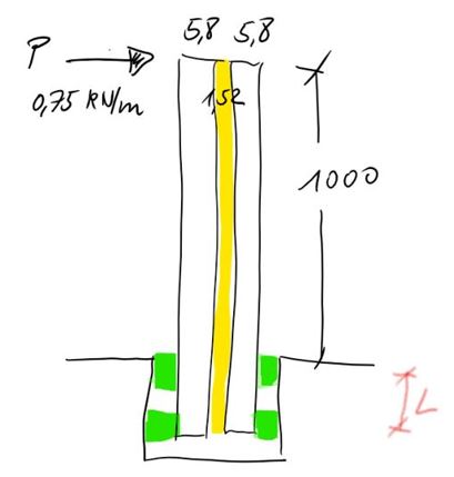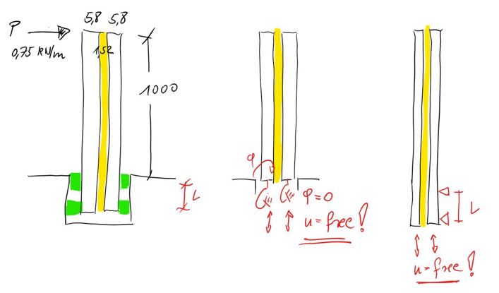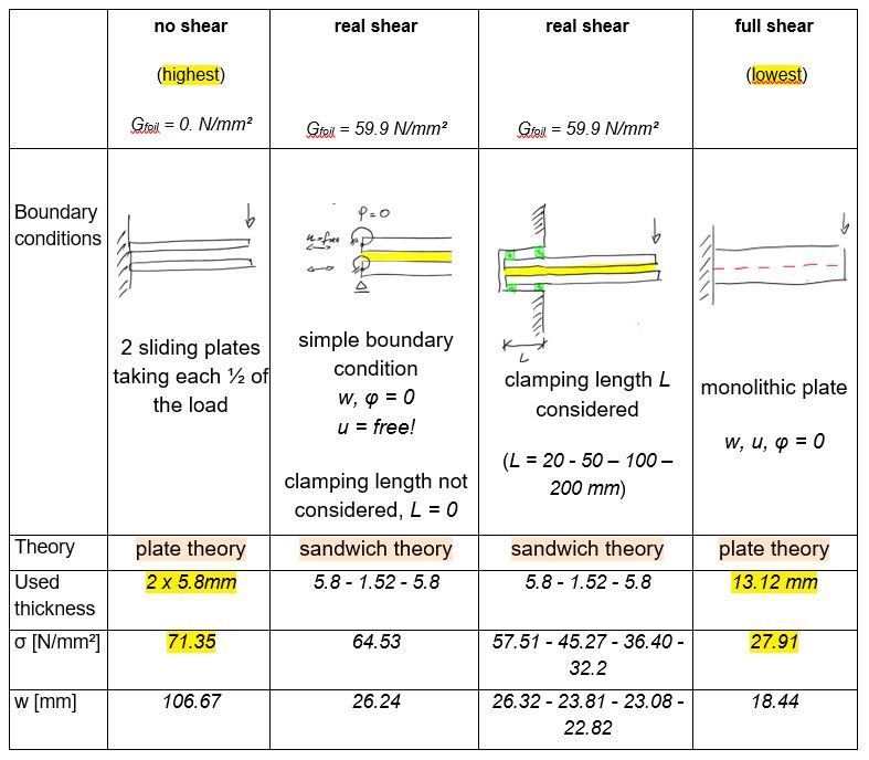

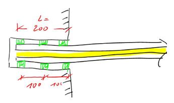
A laminated glass anchored in a glass shoe may be regarded
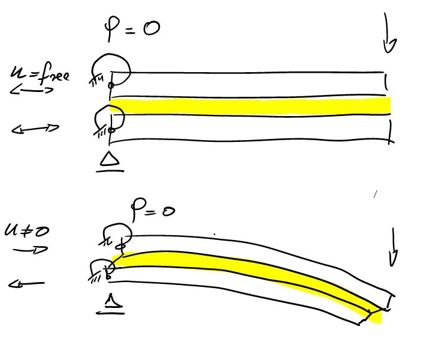
a.) as simply cut off and using nodal degrees of freedom to describe the transition conditions at this cut end. Here it’s stated that the cross section can’t rotate (φ = 0). The movements of the layers in plane direction are set free (u = free) to allow unhindered shear deformation.
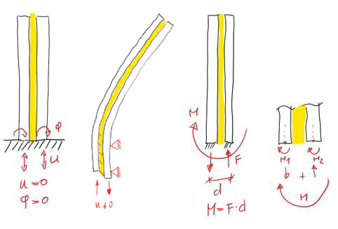
b.) using the full glass length also inside of the notch to simulate the whole behaviour of all laminated glass areas. To apply the bending moment two supporting lines of distance L are used. This is a full description of this situation.Glass can’t be fixed like shown in the picture with w, u, φ = 0. The glass ends should be able to slip so that shear deformations (u ≠ 0) are possible. If these ends are fixed in-plane direction, there will be larger reaction forces F keeping the glass end at this position and so building an additional clamping moment M = F * d, which can’t be taken over by the glass.
Such a boundary condition would imply too, that the sandwich cross section will remain flat (Bernoulli Hypothesis), what can only happen when full shear effect would act and so a monolithic glass instead of a laminated glass has been set.
FE sandwich calculations [1] by such (wrong) boundary conditions will lead to very low stresses
| σ = | 27.8 N/mm² |
| w = |
18.5 mm |
| σ = | 64.5 N/mm² |
| w = |
26.24 mm |
Checking the real behavior of a sandwich structure clamped into a notch of lenght L will demonstrate the range of stresses.
First checking the stress limits which can maximally arise in this example, will give stresses from
| Stresses N/mm² | Lowest | Highest |
| FE | 27.71 | 71.35 |
| Hand formula (Beam Theory) |
27.91 | 66.90 |
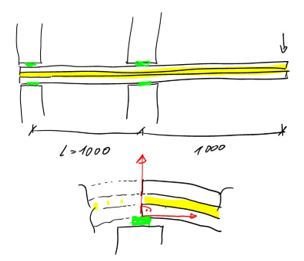
Considering a longer clamping length L will reduce the stresses to
L = 50mm → σ = 57.51 N/mm²
L = 100mm → σ = 36.40 N/mm²
L = 200 mm → σ = 32.20 N/mm²
Using again some additional in-between supports (green), forcing the section within the glass shoe to remain flat, will rise the stresses again to 35.0 N/mm².
Only in cases where L reaches the arm length of 1000 mm, the system will behave symmetrically and the cross sections in the middle will stay flat under bending.
Here the lowest stresses of 30.3 N/mm² will be found. But this solution is far away from the initial task of a balustrade clamped in a glass shoe.
This comparison shows that a balustrade can be properly designed by real sandwich theory, when all effects are considered. Here the engineer’s task will be to find good solutions providing lowest stresses. This must be done by regarding the real stiffness G of the foil, which may vary under different loading durations and temperatures. High shear stiffness will of course help to reduce the stresses. Whilst a very safe side assumption of no shear will lead to 71.35 N/mm², regarding more realistic shear effects will reduce the stresses dramatically (32.2 N/mm² by G = 59.9).
But the example shown in [1] by using an “effective laminate thickness” results in 13.02 mm to calculate stresses - so very near to fully monolithically solutions by using the sum of all layers 13.12 mm. But the laminate end is not behaving monolithically that these small stresses of 26.6 N/mm² will be correct. The comparing finite element analysis in [1] is doing just the mistake to fix the glass ends in-plane direction, so that the same too small stress result appears.
As shown above, the stresses are in real depending upon the clamping length L and the shear effect G. Even for a higher shear modulus of G = 59.9 N/mm² a monolithic solution (26.6 N/mm²) can’t be found. Just such locally clamped free sandwich edges in a balustrade will shear deform and much higher shear stiffness would be needed to act here as a monolithic plate.
Specially for sandwich structures all boundary conditions are important, also the sections which seems not directly involved like clamped parts within a glass shoe.
Sandwich behavior is much more complex than simply using one equivalent thickness value overall of the laminate.
Mentioned Literature
[1] Effective Laminate Thickness for Design of Laminated Glass, Tampere 2009, Calderone, Davies, Bennison, Xiaokun, Gang, www.sentryglas.com